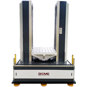
 KRD10 Hydraulic Vertical Shock Test System
KRD10 series full-automatic hydraulic shock test system is used to measure and determine the impact resistance of products or packaging, and to evaluate the reliability and structural integrity of products in a shock environment. The system can perform conventional half-sine wave, post-peak sawtooth wave, trapezoid wave and other waveform shock tests to achieve the shock wave and impact energy that the product is subjected to in the actual environment, thereby improving the product or packaging structure.
| Model Parameters | KRD 10-2 (Manual) | KRD 10-5 | KRD 10-25 | KRD 10-50 | KRD 10-100 | KRD 10-200 | KRD 10-400 | KRD 10-500 | KRD 10-600 | KRD 10-1000 | KRD 10-1500 | KRD 10-3000 | |
|---|---|---|---|---|---|---|---|---|---|---|---|---|---|
| Rated Load (kg) | 2 | 5 | 25 | 50 | 100 | 200 | 400 | 500 | 600 | 1000 | 1500 | 3000 | |
| Table Size (mm) | 115×115 | 200×200 | 300×300 | 500×500 | 600×600 | 800×600 | 800×800 | 1000×800 | 1000×1000 | 1200×1000 | 1500×1200 | 2000×1500 | |
| Peak Acc. (g) | Half-sine | 5~3k | 5~2k | 5~1.5k | 10~750 | 10~600 | 10~450 | 10~400 | 10~300 | 10~300 | 10~250 | 10~150 | 15~100 |
| Post-peak Sawtooth | 10~200 | 10~100 | 10~50 | ||||||||||
| Trapezoid | / | 15~200 | 15~100 | 15~60 | 15~50 | 30~50 | |||||||
| Pulse Duration (ms) | Half-sine | 0.3~40 | 0.5~40 | 0.6~60 | 1.5~60 | 2~60 | 2.5~60 | 3~60 | 3.5~60 | 4~60 | 4.5~60 | 6~60 | 11~40 |
| Post-peak Sawtooth | 3~18 | 6~18 | |||||||||||
| Trapezoid | / | 3~18 | 6~18 | ||||||||||
| Overall Dimensions (mm) | 450×180×2100 | 1000×900×2350 | 1400×1200×2300 | 1600×1400×2300 | 1700×1500×2300 | 1700×1500×2300 | 1900×1500×2550 | 1900×1500×2550 | 1900×1800×2550 | 1900×1800×2650 | 2200×2100×2650 | 2700×2500×3000 | |
| Weight (kg) | 200 | 1000 | 1800 | 3000 | 4200 | 4300 | 5200 | 5300 | 7000 | 8000 | 10000 | 15000 | |
| Working Environment | Temperature range 0 ~ 40℃, Humidity≤80% (non-condensing) | ||||||||||||
| Power | Control measurement: 1-phase AC220V±10% 50Hz Oil source: 3-phase 380V±10% 50Hz | ||||||||||||
| Installation Condition | Foundation-free, the cement floor shall be leveled and the working distance of 800 ~ 1000mm shall be reserved around the equipment | ||||||||||||
| Standards | MIL-STD-810 IEC68-2-27 UN38.3 IEC62281 IEC62133-2 UL2054 IEEE1625 SAEJ2929 IEC62660-2 ISO12405-3 UL2580 | ||||||||||||
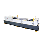
 KRD11 Pneumatic Vertical Shock Test System
KRD11 series pneumatic vertical shock test system is featured with advanced design, high degree of automation and reliability, simple operation and convenient maintenance. The system meets the requirements of both shock and bump test, can perform conventional half-sine wave, post-peak sawtooth wave, trapezoid wave and other waveform shock tests.
| Model Parameters |
KRD 11-5 |
KRD 11-15 |
KRD 11-25 |
KRD 11-50 |
KRD 11-100 |
KRD 11-200 |
KRD 11-400 |
KRD 11-600 |
KRD 11-800 |
KRD 11-1000 |
KRD 11-2000 |
|
|---|---|---|---|---|---|---|---|---|---|---|---|---|
| Rated Load (kg) | 5 | 15 | 25 | 50 | 100 | 200 | 400 | 600 | 800 | 1000 | 2000 | |
| Table Size (mm) | 150×150 | 200×200 | 300×300 | 500×500 | 600×600 | 800×600 | 800×800 | 1000×800 | 1000×1000 | 1200×1200 | 1500×1200 | |
| Peak Acc. (g) | Half-Sine | 5-2500 | 5-2000 | 5-1500 | 10-750 | 10-600 | 10-450 | 10-400 | 10-300 | 10~300 | 10~250 | 10~150 |
| Post-Peak Sawtooth | 10-200 | 10-100 | 10-50 | |||||||||
| Trapezoid | / | 15-200 | 15-100 | 15-60 | 15-50 | |||||||
| Pulse Duration (ms) | Half-Sine | 0.4~40 | 0.5~40 | 0.6~60 | 1.5~60 | 2~60 | 2.5~60 | 3~60 | 3.5~60 | 4~60 | 4.5~60 | 6~60 |
| Post-Peak Sawtooth | 3~18 | 6~18 | ||||||||||
| Trapezoid | / | 3~18 | 6~18 | |||||||||
| Bump Waveform (Optional) | Half-sine Waveform | |||||||||||
| Bump Peak Acceleration (g) | 5~150 | 5~120 | 5~100 | 5~80 | 5~60 | 5~40 | / | |||||
| Bump Pulse Duration (ms) | 2~30 | 3~30 | 4 ~ 30 | 5 ~ 30 | / | |||||||
| Bump Rate (Times/Min) | 10~120 | 10~100 | 10~80 | 10~60 | 10~40 | 10~30 | / | |||||
| Overall Dimension (mm) | 1000×1000×2100 | 1000×1000×2160 | 1510×1300×2400 | 1690×1240×2350 | 1710×1160×2350 | 1910×1500×2700 | 1910×1500×2500 | 1900×1500×2450 | 2000×1500×2450 | 1900×1800×2550 | 2200×1800×2550 | |
| Weight (kg) | 1300 | 2300 | 3000 | 3070 | 3900 | 4500 | 5000 | 5200 | 5600 | 6200 | 7300 | |
| Working Environment | Temperature range 0 ~ 40℃, Humidity≤80% (non-condensing) | |||||||||||
| Power | 1-phase AC220V±10% 50Hz | |||||||||||
| Air source | ≤0.8MPa | |||||||||||
| Installation Condition | Foundation-free, the cement floor shall be leveled and the working distance of 800~1000mm shall be reserved around the equipment | |||||||||||
| Standards | MIL-STD-810 IEC68-2-27 MIL-STD-202 MIL-STD-750 MIL-STD-883 UN38.3 IEC62281 IEC62133-2 UL2054 IEEE1625 SAEJ2929 IEC62660-2 ISO12405-3 UL2580 | |||||||||||
 KRD12 Pneumatic Horizontal Shock Test System
The KRD12 series shock test system is used to measure and determine the horizontal impact resistance of a product or package, and to evaluate the reliability and structural integrity of the test unit in a horizontal impact environment. The system can perform conventional half-sine wave, post-peak sawtooth wave, or trapezoid wave shock test to realize the shock energy that the product is subjected to in the actual environment, thereby improving the product or packaging structure.
| Model Parameters |
KRD12-10 | KRD12-50 | KRD12-100 | KRD12-200 | KRD12-500 | KRD12-1000 | KRD12-2000 | KRD12-3000 | ||||
|---|---|---|---|---|---|---|---|---|---|---|---|---|
| Rated Load (kg) | 10 | 50 | 100 | 200 | 500 | 1000 | 2000 | 3000 | ||||
| Table Size (mm) | 200×200 | 500×500 | 600×600 | 800×800 | 1000×1000 | 1200×1200 | 1500×1500 | 2000×2000 | ||||
| Peak Acc. (g) | Half-Sine | 10-5000 | 10~1500 | 10~1000 | 10-800 | 10-600 | 10-500 | 10-200 | 10-150 | |||
| Post-Peak Sawtooth | 10~200 | 10~100 | 10~50 | |||||||||
| Trapezoid | / | 15~200 | 15~200 | 15-100 | 15-60 | 15-60 | 15-50 | 30-50 | ||||
| Pulse Duration (ms) | Half-Sine | 0.3~40 | 1~60 | 1.5~60 | 2~60 | 2.5~60 | 3~60 | 6~60 | 8~60 | |||
| Post-Peak Sawtooth | 3~18 | 6~18 | ||||||||||
| Trapezoid | / | 3~18 | 6~18 | |||||||||
| Bump Waveform (Optional) | Half sine Waveform | |||||||||||
| Bump Peak Acceleration (g) | 5-150 | 5-100 | 5-80 | 5-60 | / | |||||||
| Bump Pulse Duration (ms) | 2-30 | 3-30 | 4-30 | / | ||||||||
| Bump Rate (Times/Min) | 10 ~ 120 | 10-80 | 10-60 | 10-40 | / | |||||||
| Overall Dimension (mm) | 2950×1240×1000 | 3300×1150×850 | 3500×1240×1100 | 3740×1440×1050 | 4250×1450×1100 | 4500×1650×850 | 5500×2000×850 | 6000×2200×850 | ||||
| Weight (kg) | 3700 | 3600 | 4800 | 5856 | 6500 | 7000 | 8000 | 9000 | ||||
| Working Environment | Temperature range 0~40℃, Humidity ≤ 80% (non-condensing) | |||||||||||
| Power | 1-phase AC220V±10% 50Hz | |||||||||||
| Air source | ≤1MPa | |||||||||||
| Installation Condition | Special foundation, foundation-free base is optional. The working distance of 800~1000mm shall be reserved around the equipment. | |||||||||||
| Standard | MIL-STD-810 IEC68-2-27 MIL-STD-202 MIL-STD-750 MIL-STD-883 UN38.3 IEC62281 IEC62133-2 UL2054 IEEE1625 SAEJ2929 IEC62660-2 ISO12405-3 UL2580 | |||||||||||
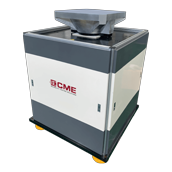 KRD13 High Energy Shock Test System
KRD13 series high energy shock test system is specially designed to meet the requirements of military and automotive testing. The system adopts the principle of pneumatic energy storage expansion. By adjusting the inflation pressure, various high-level acceleration tests can be easily implemented in a short stroke.
For the high-G classic shock test, it’s equipped with the corresponding shock amplifier to complete high-peak shock test.
| Model Parameters |
KRD13-50 | KRD13-100 | KRD13-200 | KRD13-500 | KRD13-800 | KRD13-1000 | KRD13-2000 | |
|---|---|---|---|---|---|---|---|---|
| Rated Load (kg) | 50 | 100 | 200 | 500 | 800 | 1000 | 2000 | |
| Table Size (mm) | 500×500 | 600×600 | 800×800 | 1000×1000 | 1200×1200 | 1500×1500 | 2000×2000 | |
| Peak Acc. (g) | Half-Sine | 10~1500 | 10~1000 | 10-1000 | 10-500 | 10-400 | 10-300 | 10-200 |
| Post-Peak Sawtooth | 10~200 | 10~100 | 10-50 | |||||
| Trapezoid | 15-200 | 15-100 | 15-100 | 15-60 | 15-50 | 30-50 | ||
| Pulse Duration (ms) | Half-Sine | 2~60 | 3~60 | 3~60 | 4~60 | 5~60 | 6~60 | 8~60 |
| Post-Peak Sawtooth | 3~18 | 6~18 | ||||||
| Trapezoid | 3~18 | 6~18 | ||||||
| Bump Waveform (Optional) | Half Sine Waveform | |||||||
| Bump Peak Acceleration (g) | 5~100 | 5~80 | 5~60 | 5~40 | / | |||
| Bump Pulse Duration(ms) | 3~30 | 3~30 | 4~30 | 5~30 | / | |||
| Bump Rate (Times/Min) | 10~80 | 10~60 | 10-40 | / | ||||
| Overall Dimension (mm) | 1200×1200×1500 | 1200×1200×1650 | 1100×1100×1700 | 1300×1300×1600 | 1500×1500×1700 | 1600×1600×1800 | 2000×2000×1900 | |
| Weight (kg) | 3000 | 3800 | 3200 | 4000 | 5000 | 6000 | 8500 | |
| Environment | Temperature range 0~4500℃, Humidity ≤ 80% (non-condensing) | |||||||
| Power | 1-phase AC220V±10% 50Hz | |||||||
| Air source | ≤1MPa | |||||||
| Foundation-free, the cement floor shall be leveled and adjusted and the working distance of 800~1000mm shall be reserved around the equipment | ||||||||
| Standards | IEC68-2-27 MIL-STD-202 MECD-STD-750 MIL-STD-810 MIL-STD-883 UN38.3 IEC62281 IEC62133-2 UL2054 IEEE1625 MSDS UL2580 IEC62660 MSCD12405-3 UL | |||||||
 KRD16 High Impact Shock Test System
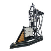
High impact shock test system meets MIL-S-901D standard which covers shock testing requirements for ship board machinery, equipment, systems, and structures, excluding submarine pressure hull penetrations. The purpose of these requirements is to verify the ability of shipboard installations to withstand shock loadings which may be incurred during wartime service due to the effects of nuclear or conventional weapons.
CME provides lightweight & medium weight high impact shock test system in accordance with one of the following test categories, as specified.
| Model Parameters | KRD16-1 | KRD16-2 |
|---|---|---|
| Lightweight | Medium weight | |
| Max Load (kg) | 200 | 3000 (Including fixtures≤3400) |
| Pendulum Mass (kg) | 182 | 1360 |
| Shock Form | Preset energy automatic completion | |
| Drop Hammer Height (mm) | 0-1500 | 0-1870 |
| Work Table Size (mm) | 4A (Flat plate) 860×570 | 1520×1520 |
| 4C-Ⅰ (Angle plate) 670×300 | ||
| 4C-Ⅱ (Angle plate) 670×300 | ||
| 4C-Ⅲ (Angle plate) 670×550 | ||
| Overall Dimension (mm) | 4800×1300×4500 | 3650×3300×3200 |
| Weight (kg) | 3000 | 15000 |
| Power | 3-phase AC380V±10% 50Hz | |
| Working Environment | Temperature range 0~40℃, Humidity ≤ 80% (non-condensing) | |
| Installation Site | According to the foundation drawings provided by the manufacturer | |
| Standards | MIL-S-901D | |
 KRD17 Pneumatic Bidirectional Vertical Shock Test System
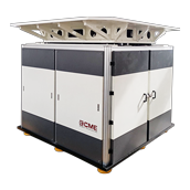
KRD17 series pneumatic bidirectional vertical shock test system is the novel designed and developed for large specimens that cannot or are not easy to turn over, especially adopt for battery testing. It can complete vertical upward and downward shock test in one test stand without moving the UUT.
| Model Parameters |
KRD17-50 | KRD17-100 | KRD17-200 | KRD17-500 | KRD17-800 | KRD17-1000 | KRD17-2000 | |
|---|---|---|---|---|---|---|---|---|
| Rated Load (kg) | 50 | 100 | 200 | 500 | 800 | 1000 | 2000 | Table Size (mm) | 500×500 | 600×600 | 800 | 1000×1000 | 1200×1200 | 1500×1500 | 2000×2000 | Shock Direction | Downward |
| Peak Acc. (g) | Half-Sine | 10-750 | 10-600 | 10-450 | 10-300 | 10-250 | 10-200 | 10-150 | Post-Peak Sawtooth | 10-100 | 10-200 | 10-100 | 10-100 | 10-100 | 10-100 | 10-100 | Trapezoid | 15-200 | 15-200 | 15-100 | 15-100 | 15-60 | 15-60 | 15-50 |
| Pulse Duration (ms) | Half-Sine | 1.5-60 | 2-60 | 2.5-60 | 4-60 | 4.5-60 | 5-60 | 6-60 | Post-Peak Sawtooth | 3~18 | 6~18 | Trapezoid | 3~18 | 3~18 | 6~18 |
| Shock Direction | Upward | |||||||
| Shock Wave | Half Sine Waveform | |||||||
| Peak Acceleration (G) | 15-350 | 15-300 | 15-200 | 15-150 | 15-100 | 15-100 | 15-75 | |
| Pulse Duration (ms) | 3.5-60 | 3.5-60 | 4-60 | 4.5-40 | 5.5-60 | 5.5-60 | 6-60 | |
| Overall Dimension (mm) | 1250×1250×1600 | 1250×1250×1600 | 1300×1300×1700 | 1350×1350×1750 | 1550×1550×1750 | 1650×1650×1850 | 2000×2000×1900 | |
| Weight (kg) | 3000 | 3200 | 3500 | 4500 | 5000 | 6000 | 8000 | |
| Power | 1-phase AC220V±10% 50Hz | |||||||
| Air Source | ≤1MPa | |||||||
| Installation Condition | Foundation-free, the cement floor shall be leveled and the working distance of 800 ~ 1000mm shall be reserved around the equipment | |||||||
| Working Environment | Temperature range 0 ~ 40℃, Humidity≤80% (non-condensing) | |||||||
| Standards | IEC68-2-27 MIL-STD-202 MIL-STD-750 MIL-STD-810 MIL-STD-883 UN38.3 IEC62281 IEC62133-2 UL2054 IEEE1625 SAEJ2929 IEC62660-2 ISO12405-3 UL2580 | |||||||
 KRD20 Pneumatic Bump Test Machine
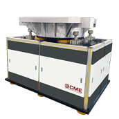
The KRD20 series pneumatic bump test machine replaces the traditional mechanical cam-type crash bench and is suitable for repeated impacts on electronic components, equipment and other electrical and electronic products during transportation or working.
| Model Parameters |
KRD20-50 | KRD20-100 | KRD20-200 | KRD20-500 | KRD20-800 | KRD20-1000 | KRD20-1500 | KRD20-2000 | KRD20-3000 |
|---|---|---|---|---|---|---|---|---|---|
| Load (kg) | 50 | 100 | 200 | 500 | 800 | 1000 | 1500 | 2000 | 3000 |
| Table Size (mm) | 500×500 | 600×600 | 800×800 | 1000×1000 | 1500×1500 | 1800×1800 | 2000×2000 | 2500×2000 | 2500×2500 |
| Shock Waveform | Half sine waveform | ||||||||
| Peak Acceleration (g) | 3~150 | 3~120 | 3~100 | 3~80 | 4~60 | 5~50 | 5~50 | 5~40 | 5~30 |
| Pulse Duration (ms) | 2~30 | 3~30 | 5~30 | 6~30 | 6~30 | 8~30 | 11~30 | ||
| Bump Rate (Times/Min) | 1~120 | 1~100 | 1-80 | 1~60 | 1~30 | 1~20 | |||
| Overall Dimension (mm) | 1050×1050×1300 | 1090×1090×1300 | 1050×1050×1280 | 1300×1300×1650 | 1500×1500×1600 | 1800×1800×1600 | 2000×2000×1850 | 2500×2000×1950 | 2500×2500×2100 |
| Weight (kg) | 1500 | 1980 | 1925 | 3475 | 2800 | 7500 | 8500 | 9500 | 11000 |
| Power Supply | 1-phase AC220V±10% 50Hz | ||||||||
| Air Source | ≤0.8Mpa | ||||||||
| Working Environment | Temperature range 0 ~ 40℃, Humidity≤80% (non-cond) | ||||||||
| Standards | MIL-STD-810 IEC68-2-29 | ||||||||